
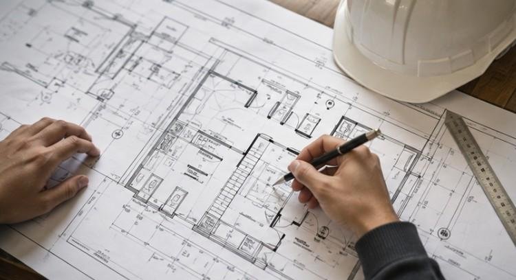
Unrolling a fresh set of construction plans can feel like trying to crack an ancient secret code. During our early days in architectural design, mastering how to read architectural blueprints transformed complex line work into living, breathing spaces. Once you learn the universal visual language architects use, reading these drawings becomes second nature for every project.
Learning how to read architectural blueprints turns confusing paper lines into X-ray vision for any project. Instead of guessing where walls go or why doors collide, you unlock the ability to spot costly design mistakes early, communicate with contractors like a seasoned professional, and bring wild architectural ideas to life without expensive job-site surprises.
Key Takeaways:
- Start every architectural review at the title block to confirm scale, sheet numbers, and design revisions.
- Learn the blueprint language by identifying solid object lines, dashed hidden lines, and dimension callouts.
- Separate spatial drawings like floor plans and elevations from trade-specific mechanical, electrical, and plumbing plans.
- Use an architect scale ruler or digital CAD viewer to accurately measure room proportions before construction.
- Cross-reference architectural notes with physical site boundaries to avoid costly placement or building errors.
Key Components of a Plan Set
Understanding the foundational documents inside a drawing set ensures you never feel lost when opening a massive blueprint binder.

Title Block Overview
Every blueprint sheet contains a title block, typically located in the lower-right corner, that acts as the official project identification panel. It provides essential information such as the project name, sheet number, drawing title, scale, issue date, designer, and revision history. Before studying the drawing itself, always check the title block to confirm that you are using the correct sheet and the latest approved revision.
Revision dates and numbers are especially important because they indicate whether changes have been made since an earlier drawing was issued. Using an outdated plan can lead to incorrect measurements, construction errors, and costly rework.
Site and Plot Plans
Site and plot plans provide a top-down overview of the entire property and show how the proposed building fits within its surroundings. These drawings typically identify property boundaries, building setbacks, access roads, driveways, parking areas, landscaping, drainage features, and utility connections. They may also indicate easements, site contours, existing structures, and underground services.
Reviewing these details helps contractors and designers understand site conditions before construction begins. A careful examination can also reveal potential access restrictions, grading requirements, or conflicts with existing utilities that could affect excavation and foundation work.
Floor Plans, Elevations, and Sections

Floor plans provide a horizontal, top-down view of a building, showing room layouts, wall locations, dimensions, door swings, windows, stairs, fixtures, and circulation areas. Elevation drawings show the building’s exterior faces from different directions, helping identify overall heights, rooflines, windows, doors, and exterior finishes.
Section drawings provide a vertical cut through the building, revealing information that may not be visible in floor plans or elevations. They can show floor levels, wall assemblies, structural connections, insulation, ceilings, foundations, and other hidden construction details. Together, these drawings create a complete picture of the building’s sustainable design.
Basic Blueprint Symbols and Lines
Lines do the heavy lifting in architectural drafting by defining physical edges, hidden structures, and spatial measurements.
Structural Lines and Partition Thickness
Solid thick lines represent primary structural boundaries or heavy load-bearing exterior walls on the plan set. Thin solid lines define minor interior partition walls, built-in shelving, or non-structural millwork items. Recognizing the weight of each line helps you immediately distinguish main support walls from simple room dividers during plan reviews.
Dashed Lines, Door Arcs, and Grids
Dashed lines indicate hidden elements or overhead features like structural ceiling beams, soffits, and upper cabinetry. Curved door arcs show the exact swing direction of doors so you can plan furniture layouts without blocking pathways.
Numbered and lettered grid lines create a clear coordinate system across large plans, making it easy to locate specific columns or job-site areas instantly.
Step-by-Step Guide: How to Read Architectural Blueprints in Real Life
Applying blueprint concepts on an active job site requires a clear, logical step-by-step review process.
Step One: Examine the Title Block and Legend
Start every review session by checking the title block for the correct sheet number, scale ratio, and latest approval stamp. Study the symbol legend sheet carefully to memorize project-specific abbreviations and material patterns before reading complex layout pages.
Step Two: Orient the Plan and Trace Pathways
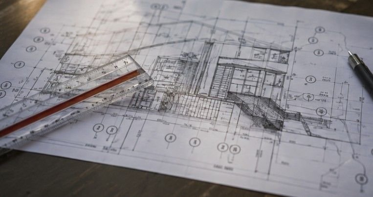
Locate the north arrow symbol on the site plan to orient the building relative to natural daylight and property lines. Perform a mental walkthrough of the primary floor plan, tracing main entries, hallway corridors, and door swing arcs to evaluate spatial flow and daily functionality.
Step Three: Verify Dimensions and Cross-References
Measure room boundaries using an architect scale ruler, cross-referencing written dimension strings against general architectural notes. Check detail callout bubbles on the floor plan that point to detailed section drawings, ensuring structural framing aligns with industry standards set by the American Institute of Architects (AIA).
Frequently Asked Questions
1. How do you read blueprints for beginners?
Begin by reviewing the title block for project details and scale. Then learn common line types, symbols, dimensions, and legends to understand rooms, walls, doors, and layouts.
2. How can I understand and interpret architectural drawings?
Start by identifying each sheet type and checking dimensions. Learn standard architectural symbols for doors, windows, walls, and fixtures, then compare floor plans, elevations, and sections.
3. How do you interpret blueprints?
Interpret blueprints by following grid lines, dimensions, symbols, and notes. Visualize how the two-dimensional drawings represent actual walls, spaces, structural elements, utilities, and finished architectural features.
4. How difficult is it to read blueprints?
Reading blueprints becomes easier with practice. Learn title blocks, scales, line weights, dimensions, symbols, and drawing conventions, then apply these skills to real architectural plans.
Unlocking Your Blueprint Mastery Fast
Understanding how to read architectural blueprints transforms creative ideas into practical, buildable realities. By carefully interpreting title blocks, scale ratios, line weights, dimensions, symbols, and trade drawings, you can confidently evaluate plans and make informed design and construction decisions.
With these skills, blueprints become more than technical documents—they become a clear roadmap for bringing your ideas to life. So, pick up your scale ruler, review your next plan set, and turn your architectural vision into a successful, well-executed project.